
Product Description
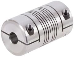
Aluminum Encoder Coupling Beam Coupling
Description of Aluminum Encoder Coupling Beam Coupling
1. One-piece metallic beam coupling
2. Zero backlash, flexible shaft
3. Spiral and parallel cut designs available
4. Accommodates misalignment and shaft endplay
5. Identical clockwise and counterclockwise rotation
6. Available in aluminum or stainless steel
7. Multiple bore and shaft connecting configurations
Parameter of Aluminum Encoder Coupling Beam Coupling
|
Model |
D (mm) |
L (mm) |
d1-d2 (mm) |
hex screw |
L1 (mm) |
L2 (mm) |
L3 (mm) |
Fasten Torque (n.m) |
|
LR-D-D15L20 |
15 |
20 |
3.0-8.0 |
M3. |
2.5 |
2 |
0.4 |
1.2 |
|
LR-D-D19L25 |
19 |
25 |
6.0-10.0 |
M3. |
3 |
2 |
0.4 |
1.2 |
|
LR-D-D25L30 |
25 |
30 |
8.0-12.0 |
M4 |
4 |
2 |
0.4 |
2.5 |
|
LR-D-D30L35 |
30 |
35 |
8.0-18.0 |
M4 |
4 |
2.5 |
0.5 |
2.5 |
|
LR-D-D35L40 |
35 |
40 |
8.0-22.0 |
M5 |
5 |
2.5 |
0.5 |
5 |
|
LR-D-D40L45 |
40 |
45 |
10.0-28.0 |
M6 |
6 |
3.5 |
0.6 |
8 |
|
Model |
Max bore (mm) |
Rated Torque (n.m) |
Max Torque (n.m) |
Max speed (rpm) |
Moment of Inertia (kg.m2) |
Permissible Radial Deviation (degree) |
Permissible Angular Deviation (degree) |
|
LR-D-D15L20 |
8 |
0.5 |
1 |
30000 |
2.5*10-7 |
0.05 |
0.5 |
|
LR-D-D19L25 |
10 |
1 |
2 |
25000 |
5.8*10-7 |
0.05 |
0.5 |
|
LR-D-D25L30 |
12 |
1.5 |
3 |
18000 |
1.8*10-6 |
0.05 |
0.5 |
|
LR-D-D30L35 |
18 |
2 |
4 |
16000 |
4.7*10-6 |
0.05 |
0.5 |
|
LR-D-D35L40 |
22 |
3 |
6 |
14000 |
1.1*10-5 |
0.05 |
0.5 |
|
LR-D-D40L45 |
28 |
6 |
12 |
12000 |
2.3*10-5 |
0.05 |
0.5 |
|
Model |
D (mm) |
L (mm) |
d1-d2 (mm) |
Fasten Torque (n.m) |
|
LT-D-D15L20 |
15 |
20 |
4.0-5.0 |
0.7 |
|
LT-D-D19L25 |
19 |
25 |
6.0-10.0 |
0.7 |
|
LT-D-D25L30 |
25 |
30 |
8.0-12.0 |
0.7 |
|
LT-D-D30L35 |
30 |
35 |
8.0-18.0 |
1.7 |
|
LT-D-D35L40 |
35 |
40 |
8.0-22.0 |
4 |
|
LT-D-D40L45 |
40 |
45 |
10.0-28.0 |
4 |
|
Model |
Max bore (mm) |
Rated Torque (n.m) |
Max Torque (n.m) |
Max speed (rpm) |
Moment of Inertia (kg.m2) |
Permissible Radial Deviation (degree) |
Permissible Angular Deviation (degree) |
|
LT-D-D15L20 |
5 |
0.5 |
1 |
30000 |
2.5*10-7 |
0.05 |
0.5 |
|
LT-D-D19L25 |
10 |
1 |
2 |
25000 |
5.8*10-7 |
0.05 |
0.5 |
|
LT-D-D25L30 |
12 |
1.5 |
3 |
18000 |
1.8*10-6 |
0.05 |
0.5 |
|
LT-D-D30L35 |
18 |
2 |
4 |
16000 |
4.7*10-6 |
0.05 |
0.5 |
|
LT-D-D35L40 |
22 |
3 |
6 |
14000 |
1.1*10-5 |
0.05 |
0.5 |
|
LT-D-D40L45 |
28 |
6 |
12 |
12000 |
2.3*10-5 |
0.05 |
0.5 |
/* March 10, 2571 17:59:20 */!function(){function s(e,r){var a,o={};try{e&&e.split(“,”).forEach(function(e,t){e&&(a=e.match(/(.*?):(.*)$/))&&1

Torque and Speed Ratings for Different Sizes and Materials of Beam Couplings
The torque and speed ratings of beam couplings vary depending on their size, design, and material composition. Different manufacturers offer beam couplings in various configurations to meet specific application requirements. Here are some general considerations regarding torque and speed ratings for different sizes and materials of beam couplings:
- Size and Design:
Beam couplings come in different sizes and designs to accommodate various shaft diameters and misalignment compensation needs. Larger beam couplings typically have higher torque ratings, as their size allows for more robust construction and increased torsional rigidity. Likewise, different designs, such as single-beam, multi-beam, or bellows couplings, can affect the torque and speed capabilities.
- Material Composition:
The choice of material for beam couplings significantly impacts their torque and speed ratings. Common materials used in beam couplings include stainless steel, aluminum, and other high-strength alloys. Stainless steel couplings generally have higher torque ratings and are more suitable for high-speed applications due to their excellent mechanical properties and resistance to wear and corrosion.
- Manufacturer Specifications:
Each manufacturer provides specific torque and speed ratings for their beam coupling products. These ratings are determined through extensive testing and analysis to ensure reliable and safe operation within the specified limits. Always refer to the manufacturer’s datasheets and technical documentation for accurate and up-to-date information on torque and speed ratings.
- Operating Environment:
The operating environment can also influence the torque and speed ratings of beam couplings. Factors such as temperature, humidity, and exposure to chemicals or harsh conditions may affect the material properties and performance of the coupling. Consider the application’s specific environment when selecting the appropriate coupling.
It is crucial to choose a beam coupling that matches the torque and speed requirements of your application. Exceeding the rated torque or speed can lead to premature wear, coupling failure, and potential damage to other system components. Conversely, selecting a coupling with excessive torque or speed capacity may result in unnecessary costs and reduced system efficiency.
When selecting a beam coupling, always consult the manufacturer’s documentation and consider the specific application requirements to ensure that the chosen coupling can handle the intended torque and speed levels effectively and safely.
Contribution of Beam Couplings to Overall Efficiency and Reliability of Motion Systems
Beam couplings play a crucial role in enhancing the overall efficiency and reliability of motion control systems in various industrial applications. Their unique design and material properties contribute to these advantages in several ways:
- High Torque Transmission:
Beam couplings provide efficient torque transmission between shafts, allowing for precise and reliable power transfer. They can handle high torque loads without introducing backlash or slippage, ensuring accurate motion control and consistent performance.
- Flexibility and Misalignment Compensation:
Beam couplings offer flexibility, allowing them to accommodate small shaft misalignments. This characteristic reduces stress on the connected components and bearings, minimizing wear and enhancing the system’s overall reliability.
- Low Inertia:
Due to their lightweight design, beam couplings have low inertia, which means they have minimal impact on the system’s acceleration and deceleration. This low inertia helps in achieving faster response times and smoother motion profiles, improving the overall efficiency of the system.
- Vibration Dampening:
Beam couplings dampen vibrations and absorb shocks generated during operation. By reducing vibrational energy transmission, they minimize the risk of resonance and prevent premature wear or damage to the motion system components.
- Wide Range of Sizes and Materials:
Manufacturers offer beam couplings in various sizes and materials to suit different application requirements. This versatility allows for optimal coupling selection based on factors such as torque capacity, shaft diameter, and environmental conditions, ensuring an efficient and reliable coupling solution.
- Easy Installation and Maintenance:
Beam couplings are relatively simple to install and maintain. Their clamp or set screw mounting methods simplify the coupling assembly process. Additionally, routine maintenance, such as lubrication and visual inspections, helps extend their lifespan and ensures continuous system reliability.
- Non-Magnetic and Electrical Isolation Options:
Some beam couplings are available in non-magnetic materials, such as plastic or brass, which are suitable for applications where magnetic interference must be minimized. Additionally, plastic couplings offer electrical isolation properties, making them useful in applications requiring electrical insulation.
Overall, beam couplings contribute significantly to the overall efficiency and reliability of motion systems by providing precise torque transmission, compensating for misalignment, minimizing vibrations, and offering a broad range of options to meet diverse application needs. Their durable construction and ease of installation make them a dependable choice for motion control in various industrial settings.

Considerations for Using Beam Couplings in High-Speed Applications
When using beam couplings in high-speed applications, several specific considerations are essential to ensure optimal performance, safety, and reliability. High-speed operation introduces additional challenges that need to be addressed to maximize the benefits of beam couplings. Here are the key considerations:
- 1. Balance and Runout:
Ensure that the beam coupling and connected components are well-balanced and have minimal runout. Imbalanced couplings can cause vibration and resonance at high speeds, leading to reduced precision and potential damage to the system. Minimizing runout helps maintain smooth and stable operation.
- 2. Material Selection:
Choose high-quality materials for the beam coupling that can withstand the forces and stresses experienced during high-speed operation. High-strength alloys, such as stainless steel or aluminum, are commonly used for beam couplings in high-speed applications due to their excellent mechanical properties and fatigue resistance.
- 3. Torsional Rigidity:
Consider the required torsional rigidity for your specific high-speed application. While beam couplings offer good torsional rigidity, extremely high-speed applications might demand specialized couplings with even higher rigidity to ensure accurate torque transmission and minimize torsional deformation.
- 4. Critical Speed:
Be aware of the critical speed of the beam coupling, which is the rotational speed at which the coupling’s natural frequency coincides with the operating speed. At critical speed, the coupling can experience excessive vibration and become susceptible to resonance, leading to potential failure. Operating below the critical speed is essential to avoid such issues.
- 5. Lubrication:
For high-speed applications, proper lubrication of the beam coupling is crucial to reduce friction, wear, and heat generation. Lubrication also helps dissipate any generated heat, maintaining the coupling’s integrity during prolonged operation.
- 6. Cooling:
In applications with extended high-speed operation, consider implementing cooling mechanisms to prevent overheating of the beam coupling. Excessive heat can affect the material properties and lead to premature wear or failure.
- 7. Dynamic Balancing:
For high-speed systems, it is essential to dynamically balance the rotating components, including the beam coupling, to minimize vibration and prevent potential damage to the system and surrounding equipment.
- 8. Regular Inspection and Maintenance:
Perform regular inspections and maintenance to detect any signs of wear, fatigue, or misalignment in the beam coupling. Addressing issues promptly can prevent unexpected failures and costly downtime.
By carefully considering these factors and ensuring proper selection, installation, and maintenance of beam couplings in high-speed applications, you can enhance performance, extend the life of the coupling, and promote safe and reliable operation in your motion control system.


editor by CX 2024-01-23