
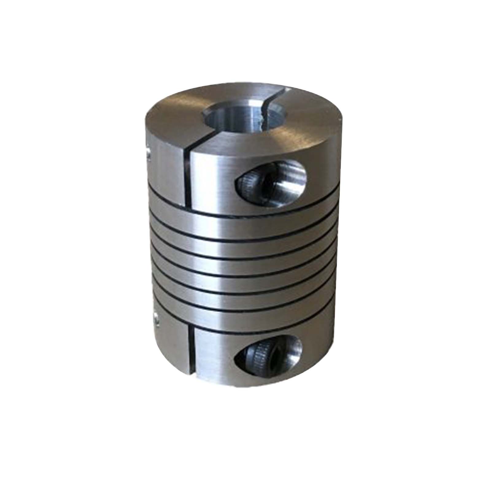
Product Description
| Product Name | Coupling | Place of origin | China |
| Brand | 1008-5050,6050-12100 | Material | Cast Iron GG22-GG25,Steel C45 |
| QD Bushing model | H/JA/SH/SDS/SD/SK/SF/E/F/J/M/N/P/W/S,orG/H/P1/P2/P3/B/Q1/Q2/Q3/R1/R2/S1/S2/U0 /U1/U2/W1/W2/Y0 |
||
1. Engineering: machine tools, foundry equipments, conveyors, compressors, painting systems, etc.
2. Pharmaceuticals& Food Processing: pulp mill blowers, conveyor in warehouse, agitators, grain, boiler, bakery machine, labeling machine, robots, etc.
3. Agriculture Industries: cultivator, rice winnower tractor, harvester, rice planter, farm equipment, etc.
4. Texitile Mills: looms, spinning, wrappers, high-speed auto looms, processing machine, twister, carding machine, ruler calendar machine, high speed winder, etc.
5. Printing Machinery: newspaper press, rotary machine, screen printer machine, linotype machine offset printer, etc.
6. Paper Industries: chipper roll grinder, cut off saw, edgers, flotation cell and chips saws, etc.
7. Building Construction Machinery: buffers, elevator floor polisher mixing machine, vibrator, hoists, crusher, etc.
8. Office Equipments: typewriter, plotters, camera, money drive, money sorting machine, data storage equipment, etc.
9. Glass and Plastic Industries: conveyor, carton sealers, grinders, creeper paper manufacturing machine, lintec backing, etc.
10. Home Appliances: vacuum cleaner, laundry machine, icecream machine, sewing machine, kitchen equipments, etc.
/* January 22, 2571 19:08:37 */!function(){function s(e,r){var a,o={};try{e&&e.split(“,”).forEach(function(e,t){e&&(a=e.match(/(.*?):(.*)$/))&&1
Temperature and Environmental Limits for Various Beam Coupling Materials
The temperature and environmental limits of beam coupling materials depend on their specific composition and properties. Different materials have varying degrees of resistance to temperature extremes, chemicals, humidity, and other environmental factors. Here are some common beam coupling materials and their associated temperature and environmental limits:
- 1. Stainless Steel:
Stainless steel beam couplings are known for their excellent mechanical properties and resistance to corrosion. They can typically operate within a wide temperature range, from -40°C to 300°C (-40°F to 572°F). Stainless steel is also resistant to most chemicals, making it suitable for various environments, including industrial and outdoor applications.
- 2. Aluminum:
Aluminum beam couplings offer lightweight construction and moderate mechanical properties. They have a more limited temperature range compared to stainless steel, typically operating between -20°C to 120°C (-4°F to 248°F). While aluminum has good corrosion resistance in certain environments, it is not as durable as stainless steel in harsh conditions.
- 3. Brass:
Brass beam couplings have reasonable mechanical properties and corrosion resistance. They are suitable for applications with temperatures ranging from -20°C to 100°C (-4°F to 212°F). Brass is more susceptible to corrosion in certain environments, so it is essential to consider the specific application’s conditions.
- 4. Plastic/Polymer:
Beam couplings made from plastic or polymer materials offer lightweight and cost-effective solutions. However, their temperature limits are more restricted compared to metal couplings. They typically operate between -30°C to 80°C (-22°F to 176°F). These couplings may not be suitable for high-temperature or chemically aggressive environments.
- 5. Carbon Steel:
Carbon steel beam couplings are known for their strength and mechanical properties. They generally operate between -40°C to 120°C (-40°F to 248°F). Carbon steel is vulnerable to corrosion, so it may not be ideal for applications in corrosive or humid environments without proper protection.
It’s crucial to consider the temperature and environmental conditions of your specific application when selecting a beam coupling material. Choosing a material that can withstand the intended operating conditions will ensure the longevity and reliable performance of the coupling.
Additionally, keep in mind that various beam coupling manufacturers may offer specific variations of materials with different properties and limits. Always refer to the manufacturer’s datasheets and technical documentation for precise information on the temperature and environmental limits of their beam coupling products.
Real-World Examples of Successful Beam Coupling Installations and Their Benefits
Beam couplings have been widely adopted in various industries, and there are numerous real-world examples of successful installations showcasing their benefits. Here are some specific cases:
- Industrial Automation:
In a factory automation setting, beam couplings are used in robotic arms and automated machinery to transmit torque between motors and actuators. The flexibility of beam couplings helps compensate for minor misalignments, reducing wear on connected components and enhancing system reliability. Additionally, the low inertia of beam couplings enables faster response times, improving the overall efficiency of the automated systems.
- Medical Robotics:
Medical robots, such as surgical robots and diagnostic equipment, rely on precise and smooth motion control. Beam couplings, with their low backlash and high torsional stiffness, ensure accurate positioning and reduced vibration. The stainless-steel construction of some medical-grade beam couplings makes them suitable for sterilization processes, ensuring compliance with medical industry requirements.
- Photonic Systems:
In optical systems and laser equipment, beam couplings are used to connect stepper motors and motion stages. The damping properties of beam couplings help reduce vibrations, preventing optical misalignment and maintaining the stability of laser beams. This is critical for high-precision applications like laser cutting and micromachining.
- Satellite Components:
Beam couplings find applications in satellite components, where weight and size constraints are critical. Aluminum or lightweight alloys are used to minimize the overall mass while providing reliable power transmission between actuators and mechanisms. The low inertia of beam couplings contributes to smoother satellite movements and precise adjustments in space.
- Renewable Energy Systems:
Beam couplings are employed in renewable energy systems, such as solar tracking mechanisms and wind turbine pitch control systems. Their ability to handle harsh environmental conditions, such as wind and weather exposure, ensures consistent and efficient energy production. The use of non-magnetic materials in some couplings prevents interference with sensitive electronics.
The benefits of successful beam coupling installations in these real-world examples include:
- Improved Precision: Beam couplings provide accurate torque transmission, reducing positioning errors and enhancing the precision of motion control systems.
- Enhanced Reliability: The flexibility of beam couplings compensates for misalignments, reducing stress on connected components and extending the lifespan of the motion system.
- Reduced Vibrations: Beam couplings dampen vibrations, leading to smoother movements and preventing resonance-induced failures.
- Weight and Space Savings: In applications with weight and space constraints, beam couplings’ lightweight design is advantageous.
- Cost-Effectiveness: Beam couplings offer a cost-effective solution for motion control, especially when compared to more complex coupling options.
These successful installations demonstrate the versatility and effectiveness of beam couplings across various industries, highlighting their ability to improve motion system performance, reliability, and efficiency.
Handling Misalignment and Compensating for Shaft Offset in Beam Couplings
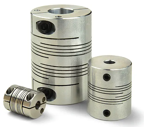
Beam couplings are designed to handle misalignment between connected shafts and compensate for shaft offset in motion control systems. Their flexible and helical beam structure allows them to accommodate various types of misalignment, ensuring smooth and reliable operation. Here’s how beam couplings handle misalignment and compensate for shaft offset:
- Helical Beam Design:
Beam couplings consist of one or more helical beams, which are thin, flexible metal strips arranged in a helix shape. The helical beam design gives beam couplings their characteristic flexibility, allowing them to bend and twist in response to misalignment and shaft offset.
- Angular Misalignment:
If the connected shafts are not collinear and are at an angle to each other, it results in angular misalignment. Beam couplings can handle angular misalignment by allowing the helical beams to flex, bending at an angle to accommodate the misaligned shafts. The flexibility of the beams enables the coupling to transmit torque smoothly even when the shafts are not perfectly aligned.
- Axial Misalignment:
Axial misalignment occurs when the two shafts are not on the same axis or are not aligned in the same line. Beam couplings can compensate for axial misalignment by permitting the helical beams to elongate or compress in the axial direction. This axial flexibility allows the coupling to accommodate the offset between the shafts without causing excessive stress on the components.
- Parallel Misalignment:
Parallel misalignment refers to the situation where the two shafts are not at the same height or parallel to each other. Beam couplings handle parallel misalignment by permitting the helical beams to shift laterally. This lateral movement allows the coupling to adjust to the offset between the shafts and maintain an effective connection.
- Compensation Range:
Beam couplings have a specified range of misalignment they can accommodate. The amount of misalignment they can handle depends on the number of helical beams and the design of the coupling. Multi-beam couplings typically have a higher misalignment compensation range compared to single-beam couplings, making them more suitable for applications with more significant misalignment requirements.
- Limitations:
While beam couplings can compensate for a certain degree of misalignment, they do have limitations. Excessive misalignment beyond the coupling’s rated capacity can lead to premature wear, increased stress on the components, and reduced coupling performance. It’s essential to operate the beam coupling within its specified misalignment limits to ensure optimal functioning and longevity.
In summary, beam couplings handle misalignment and compensate for shaft offset by virtue of their flexible helical beam design. The ability to bend, twist, elongate, and shift laterally enables them to accommodate angular, axial, and parallel misalignment in motion control systems. Choosing the appropriate beam coupling type and staying within its rated misalignment range are essential to ensure effective compensation and reliable operation in various applications.


editor by CX 2024-04-08