
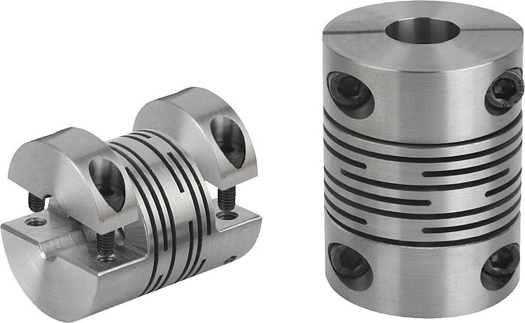
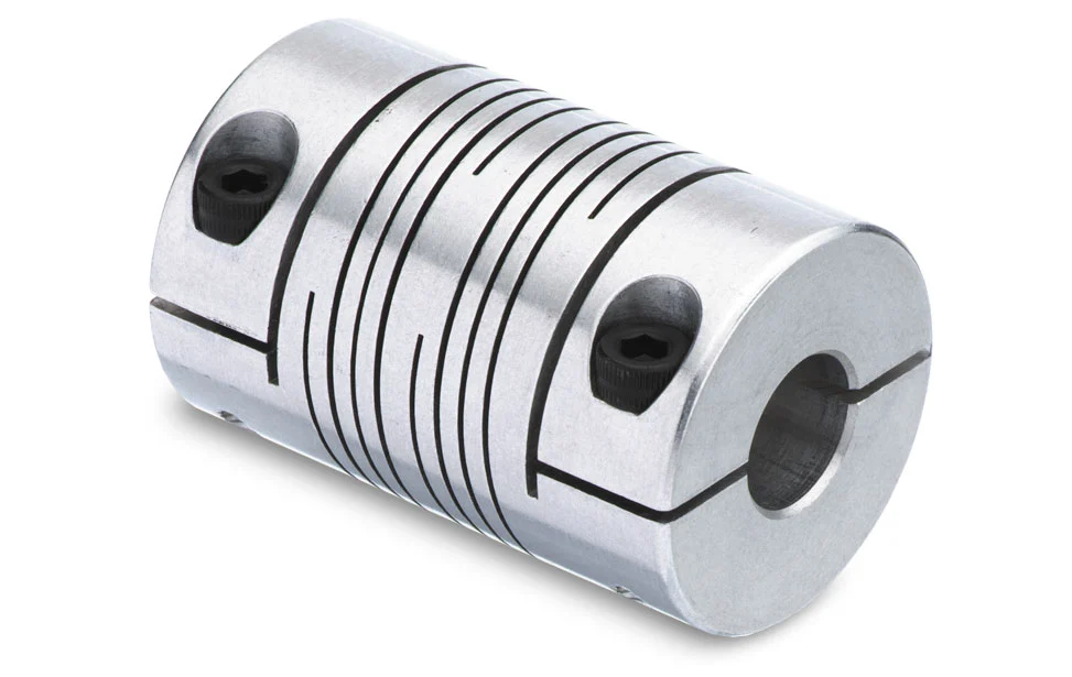
Product Description
Flexible Beam Coupling Shaft Coupling
Description of Flexible Beam Coupling Shaft Coupling
1. One-piece metallic beam coupling
2. Zero backlash, flexible shaft
3. Spiral and parallel cut designs available
4. Accommodates misalignment and shaft endplay
5. Identical clockwise and counterclockwise rotation
6. Available in aluminum or stainless steel
7. Multiple bore and shaft connecting configurations
Parameter of Flexible Beam Coupling Shaft Coupling
|
Model |
D (mm) |
L (mm) |
d1-d2 (mm) |
hex screw |
L1 (mm) |
L2 (mm) |
L3 (mm) |
Fasten Torque (n.m) |
|
LR-D-D15L20 |
15 |
20 |
3.0-8.0 |
M3. |
2.5 |
2 |
0.4 |
1.2 |
|
LR-D-D19L25 |
19 |
25 |
6.0-10.0 |
M3. |
3 |
2 |
0.4 |
1.2 |
|
LR-D-D25L30 |
25 |
30 |
8.0-12.0 |
M4 |
4 |
2 |
0.4 |
2.5 |
|
LR-D-D30L35 |
30 |
35 |
8.0-18.0 |
M4 |
4 |
2.5 |
0.5 |
2.5 |
|
LR-D-D35L40 |
35 |
40 |
8.0-22.0 |
M5 |
5 |
2.5 |
0.5 |
5 |
|
LR-D-D40L45 |
40 |
45 |
10.0-28.0 |
M6 |
6 |
3.5 |
0.6 |
8 |
|
Model |
Max bore (mm) |
Rated Torque (n.m) |
Max Torque (n.m) |
Max speed (rpm) |
Moment of Inertia (kg.m2) |
Permissible Radial Deviation (degree) |
Permissible Angular Deviation (degree) |
|
LR-D-D15L20 |
8 |
0.5 |
1 |
30000 |
2.5*10-7 |
0.05 |
0.5 |
|
LR-D-D19L25 |
10 |
1 |
2 |
25000 |
5.8*10-7 |
0.05 |
0.5 |
|
LR-D-D25L30 |
12 |
1.5 |
3 |
18000 |
1.8*10-6 |
0.05 |
0.5 |
|
LR-D-D30L35 |
18 |
2 |
4 |
16000 |
4.7*10-6 |
0.05 |
0.5 |
|
LR-D-D35L40 |
22 |
3 |
6 |
14000 |
1.1*10-5 |
0.05 |
0.5 |
|
LR-D-D40L45 |
28 |
6 |
12 |
12000 |
2.3*10-5 |
0.05 |
0.5 |
|
Model |
D (mm) |
L (mm) |
d1-d2 (mm) |
Fasten Torque (n.m) |
|
LT-D-D15L20 |
15 |
20 |
4.0-5.0 |
0.7 |
|
LT-D-D19L25 |
19 |
25 |
6.0-10.0 |
0.7 |
|
LT-D-D25L30 |
25 |
30 |
8.0-12.0 |
0.7 |
|
LT-D-D30L35 |
30 |
35 |
8.0-18.0 |
1.7 |
|
LT-D-D35L40 |
35 |
40 |
8.0-22.0 |
4 |
|
LT-D-D40L45 |
40 |
45 |
10.0-28.0 |
4 |
|
Model |
Max bore (mm) |
Rated Torque (n.m) |
Max Torque (n.m) |
Max speed (rpm) |
Moment of Inertia (kg.m2) |
Permissible Radial Deviation (degree) |
Permissible Angular Deviation (degree) |
|
LT-D-D15L20 |
5 |
0.5 |
1 |
30000 |
2.5*10-7 |
0.05 |
0.5 |
|
LT-D-D19L25 |
10 |
1 |
2 |
25000 |
5.8*10-7 |
0.05 |
0.5 |
|
LT-D-D25L30 |
12 |
1.5 |
3 |
18000 |
1.8*10-6 |
0.05 |
0.5 |
|
LT-D-D30L35 |
18 |
2 |
4 |
16000 |
4.7*10-6 |
0.05 |
0.5 |
|
LT-D-D35L40 |
22 |
3 |
6 |
14000 |
1.1*10-5 |
0.05 |
0.5 |
|
LT-D-D40L45 |
28 |
6 |
12 |
12000 |
2.3*10-5 |
0.05 |
0.5 |
/* January 22, 2571 19:08:37 */!function(){function s(e,r){var a,o={};try{e&&e.split(“,”).forEach(function(e,t){e&&(a=e.match(/(.*?):(.*)$/))&&1
Contribution of Beam Couplings to Dampening Vibrations and Reducing Resonance
Beam couplings play a significant role in dampening vibrations and reducing resonance in motion control systems. Their unique design and material properties contribute to this effect in the following ways:
- Helical Beam Design:
Beam couplings consist of helical beams that provide flexibility and torsional elasticity. When subjected to vibrations or dynamic loads, the helical beams can absorb and dampen these oscillations. The ability to flex and twist helps in dissipating vibrational energy and preventing it from propagating through the system.
- Vibration Absorption:
Beam couplings are designed to be relatively compliant, which allows them to absorb vibrations and shocks generated during operation. This absorption capability is especially beneficial when dealing with high-speed applications or systems with rapid accelerations and decelerations.
- Reduced Resonance:
Resonance occurs when the natural frequency of a system matches the frequency of external vibrations or disturbances. This phenomenon can lead to excessive vibration amplitudes, potentially causing damage or affecting the system’s performance. Beam couplings’ torsional elasticity helps to mitigate the risk of resonance by altering the system’s natural frequency, reducing the likelihood of resonance occurring within the operating range.
- Material Selection:
The choice of materials for beam couplings also contributes to their ability to dampen vibrations. Materials with good damping characteristics, such as certain alloys or elastomers, are commonly used to manufacture beam couplings. These materials can dissipate vibrational energy as heat, minimizing the transmission of vibrations to other system components.
- Shock Absorption:
In addition to dampening vibrations, beam couplings can absorb shocks or sudden impact loads. When the system experiences sudden changes in load or abrupt movements, the flexible nature of beam couplings helps to cushion and distribute the shock, protecting the machinery and reducing stress on the connected components.
Overall, the combination of the helical beam design, vibration absorption properties, reduced resonance, and appropriate material selection makes beam couplings effective in dampening vibrations and enhancing the overall stability and performance of motion control systems. When properly selected and installed, beam couplings can contribute to smoother and quieter operation, increased system reliability, and reduced wear and tear on critical components.
Beam Couplings Accommodating Different Shaft Diameters and Mounting Configurations
Beam couplings are highly versatile and can accommodate different shaft diameters and mounting configurations, making them suitable for a wide range of motion control applications. Their design and construction allow for flexibility in adapting to various shaft sizes and mounting setups. Here’s how beam couplings achieve this:
- Multiple Bore Sizes:
Beam couplings are available in various bore sizes to match different shaft diameters. Manufacturers offer a wide range of coupling sizes, ensuring that there is an appropriate coupling size available to fit the specific shaft diameter of your application. Some beam couplings come with set screws or clamps that securely fasten onto the shafts, accommodating shafts of different sizes within the coupling’s specified range.
- Clamp or Set Screw Mounting:
Beam couplings commonly employ clamp or set screw mounting methods to connect to the shafts. Clamp-style couplings use split hubs that can be tightened around the shaft with screws, providing a secure and concentric connection. Set screw couplings, on the other hand, utilize screws to press against the shaft, achieving a firm and non-marring grip.
- Step Bores and Adapters:
In cases where the shafts have significantly different diameters or when transitioning between metric and imperial measurements, some beam couplings offer step bores or adapter options. Step bores feature multiple bore sizes within the same coupling, allowing for flexibility in accommodating various shaft diameters. Adapters are also available to bridge the gap between different shaft sizes.
- Customization:
For unique or specialized applications, manufacturers may offer customization options for beam couplings. This could include modifying the bore sizes, lengths, or other design parameters to suit specific shaft dimensions and mounting configurations.
- Compatibility with Misalignment:
Beam couplings are designed to handle misalignment between the shafts. This characteristic provides additional flexibility during installation, as it can compensate for slight positioning errors or misalignment during assembly.
When selecting a beam coupling for your application, ensure that the chosen coupling size matches the shaft diameters within the specified range. Also, consider the mounting method that best suits your setup, whether it’s clamp-style or set screw-type. For applications with specific requirements, such as adapting between different shaft sizes, explore options with step bores or adapters or inquire about custom solutions from coupling manufacturers.
Overall, the ability of beam couplings to accommodate different shaft diameters and mounting configurations makes them a versatile and widely-used choice in motion control systems across various industries.

Considerations for Using Beam Couplings in High-Speed Applications
When using beam couplings in high-speed applications, several specific considerations are essential to ensure optimal performance, safety, and reliability. High-speed operation introduces additional challenges that need to be addressed to maximize the benefits of beam couplings. Here are the key considerations:
- 1. Balance and Runout:
Ensure that the beam coupling and connected components are well-balanced and have minimal runout. Imbalanced couplings can cause vibration and resonance at high speeds, leading to reduced precision and potential damage to the system. Minimizing runout helps maintain smooth and stable operation.
- 2. Material Selection:
Choose high-quality materials for the beam coupling that can withstand the forces and stresses experienced during high-speed operation. High-strength alloys, such as stainless steel or aluminum, are commonly used for beam couplings in high-speed applications due to their excellent mechanical properties and fatigue resistance.
- 3. Torsional Rigidity:
Consider the required torsional rigidity for your specific high-speed application. While beam couplings offer good torsional rigidity, extremely high-speed applications might demand specialized couplings with even higher rigidity to ensure accurate torque transmission and minimize torsional deformation.
- 4. Critical Speed:
Be aware of the critical speed of the beam coupling, which is the rotational speed at which the coupling’s natural frequency coincides with the operating speed. At critical speed, the coupling can experience excessive vibration and become susceptible to resonance, leading to potential failure. Operating below the critical speed is essential to avoid such issues.
- 5. Lubrication:
For high-speed applications, proper lubrication of the beam coupling is crucial to reduce friction, wear, and heat generation. Lubrication also helps dissipate any generated heat, maintaining the coupling’s integrity during prolonged operation.
- 6. Cooling:
In applications with extended high-speed operation, consider implementing cooling mechanisms to prevent overheating of the beam coupling. Excessive heat can affect the material properties and lead to premature wear or failure.
- 7. Dynamic Balancing:
For high-speed systems, it is essential to dynamically balance the rotating components, including the beam coupling, to minimize vibration and prevent potential damage to the system and surrounding equipment.
- 8. Regular Inspection and Maintenance:
Perform regular inspections and maintenance to detect any signs of wear, fatigue, or misalignment in the beam coupling. Addressing issues promptly can prevent unexpected failures and costly downtime.
By carefully considering these factors and ensuring proper selection, installation, and maintenance of beam couplings in high-speed applications, you can enhance performance, extend the life of the coupling, and promote safe and reliable operation in your motion control system.


editor by CX 2024-04-13