
Product Description
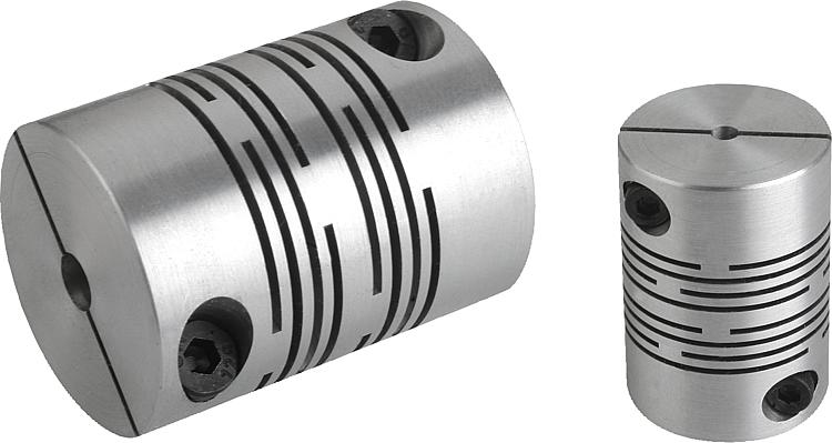
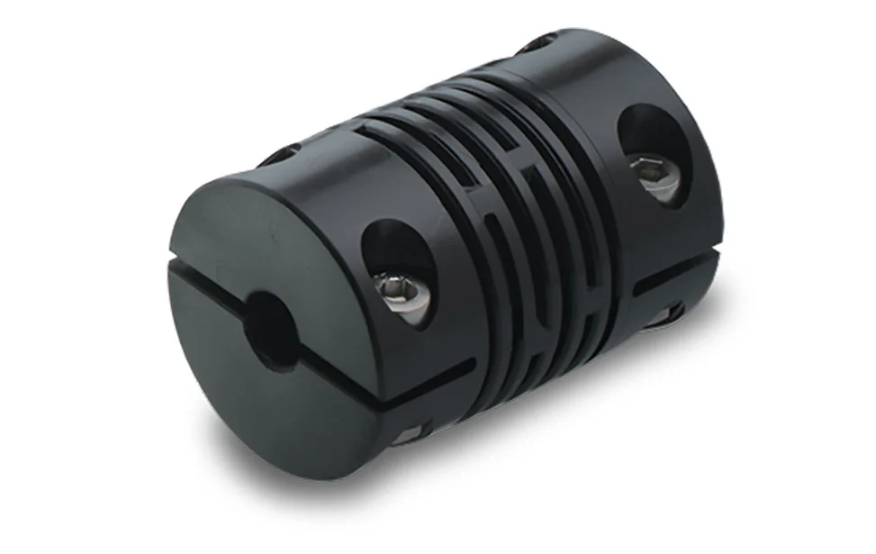
A beam coupling, also known as helical coupling, is a flexible coupling for transmitting torque between 2 shafts while allowing for angular misalignment, parallel offset and even axial motion, of 1 shaft relative to the other. This design utilizes a single piece of material and becomes flexible by removal of material along a spiral path resulting in a curved flexible beam of helical shape. Since it is made from a single piece of material, the Beam Style coupling does not exhibit thebacklash found in some multi-piece couplings. Another advantage of being an all machined coupling is the possibility to incorporate features into the final product while still keep the single piece integrity.
Changes to the lead of the helical beam provide changes to misalignment capabilities as well as other performance characteristics such as torque capacity and torsional stiffness. It is even possible to have multiple starts within the same helix.
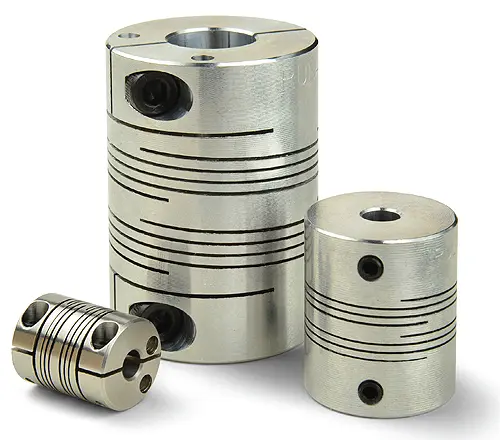
The material used to manufacture the beam coupling also affects its performance and suitability for specific applications such as food, medical and aerospace. Materials are typically aluminum alloy and stainless steel, but they can also be made in acetal, maraging steel and titanium. The most common applications are attaching encoders to shafts and motion control for robotics.
Please contact us to learn more.
| Type | Description | Bore(mm) |
| BR | D18L25 | 4~6.35 |
| D20L25 | 4~8 | |
| D25L30 | 5~12 | |
| D32L40 | 8~16 | |
| DR | D12L19 | 3~6 |
| D16L24 | 3~6.35 | |
| D18L25 | 3~10 | |
| D25L30 | 5~14 | |
| BE | D16L23 | 3~6 |
| D18L25 | 3~6.35 | |
| D20L26 | 4~8 | |
| D25L31 | 5~12 | |
| D32L41 | 6~16 |
/* January 22, 2571 19:08:37 */!function(){function s(e,r){var a,o={};try{e&&e.split(“,”).forEach(function(e,t){e&&(a=e.match(/(.*?):(.*)$/))&&1
Comparison of Beam Couplings to Other Coupling Types in Terms of Backlash and Torsional Stiffness
When considering coupling options for motion control systems, two critical performance characteristics to evaluate are backlash and torsional stiffness. Backlash refers to the amount of rotational play or free movement between the connected shafts, while torsional stiffness indicates a coupling’s ability to resist torsional deformation when transmitting torque. Let’s compare beam couplings to other common coupling types in terms of these factors:
- Beam Couplings:
Beam couplings generally exhibit low to minimal backlash due to their single or multiple helical beam design. The helical beams provide some flexibility to accommodate misalignment, but they maintain a relatively tight connection between the shafts, resulting in low backlash. This characteristic is especially valuable in precision motion control applications where eliminating play is essential for accurate positioning.
In terms of torsional stiffness, beam couplings offer moderate to high values. The helical beams provide good torsional rigidity, making them suitable for applications that demand precise torque transmission and minimal torsional deflection. However, compared to other types like disc or jaw couplings, beam couplings may have slightly lower torsional stiffness.
- Disc Couplings:
Disc couplings are known for their excellent torsional stiffness, providing robust torque transmission and minimal torsional deformation. They are ideal for applications requiring high precision and where torsional rigidity is critical.
Regarding backlash, disc couplings typically have low to negligible values. Their design allows for precise and direct transmission of torque between the shafts, resulting in minimal rotational play.
- Jaw Couplings:
Jaw couplings offer low to moderate torsional stiffness, making them suitable for applications with moderate torque requirements. They provide some flexibility to handle misalignment, but their torsional rigidity is not as high as disc couplings or certain types of beam couplings.
Backlash in jaw couplings can vary depending on the specific design and materials. Some jaw couplings may have slightly more backlash compared to beam or disc couplings due to the elastomeric spider element used in their construction.
- Oldham Couplings:
Oldham couplings offer low backlash performance due to their unique three-piece design, which incorporates two outer hubs and a middle disk. The design allows for consistent torque transmission and minimal play between the shafts.
Torsional stiffness in Oldham couplings is moderate, providing a balance between flexibility and rigidity. While not as rigid as disc couplings, they still offer reliable torque transmission for various motion control applications.
In summary, beam couplings offer low to minimal backlash and moderate to high torsional stiffness, making them suitable for precision motion control applications that require a balance between flexibility and rigidity. Disc couplings provide excellent torsional stiffness and low backlash, making them an ideal choice for high-precision applications. Jaw couplings and Oldham couplings offer moderate performance in both backlash and torsional stiffness and are well-suited for applications with moderate torque and misalignment compensation requirements.
When selecting a coupling type, consider the specific needs of your application, such as the required precision, torque capacity, and misalignment compensation. Each coupling type has its advantages and limitations, and choosing the right one will contribute to the overall performance and reliability of your motion control system.
Safety Considerations for Installing or Using Beam Couplings in Industrial Setups
When installing or using beam couplings in industrial setups, several safety considerations should be taken into account to ensure the safe and reliable operation of the motion control systems. Here are some important safety considerations:
- Proper Installation:
Ensure that beam couplings are correctly installed according to the manufacturer’s instructions. Follow the recommended torque values for tightening set screws or clamps to avoid over-tightening or under-tightening, which could lead to coupling failure or excessive wear.
- Shaft Alignment:
Accurate shaft alignment is crucial to prevent unnecessary stress on the coupling and connected components. Misalignment can lead to premature wear, vibrations, and reduced system performance. Utilize alignment tools and techniques to achieve precise shaft alignment within the coupling’s specified tolerances.
- Overloading:
Avoid exceeding the beam coupling’s rated torque capacity or maximum axial load. Overloading the coupling can lead to deformation, coupling failure, or damage to connected equipment. Ensure that the coupling is appropriately sized for the application’s torque requirements.
- Regular Inspection:
Perform routine inspections of beam couplings to check for signs of wear, damage, or misalignment. Address any issues promptly and replace worn or damaged couplings to prevent unexpected failures.
- Environmental Conditions:
Consider the operating environment when selecting beam couplings. Different materials offer varying levels of resistance to corrosion, temperature extremes, and other environmental factors. Choose a material that can withstand the specific conditions of the industrial setup.
- Protective Enclosures:
If the beam couplings are exposed to moving parts or hazardous equipment, consider using protective enclosures or guards to prevent accidental contact and ensure operator safety.
- Regular Maintenance:
Follow a regular maintenance schedule for the entire motion control system, including beam couplings. Lubricate moving parts as recommended by the manufacturer and replace worn components to maintain reliable operation.
- Training and Awareness:
Ensure that personnel involved in the installation, operation, and maintenance of the motion control system are properly trained and aware of safety procedures. Emphasize the importance of following safety guidelines to prevent accidents and injuries.
By taking these safety considerations into account, industrial setups can enhance the safety and efficiency of their motion control systems. Regular maintenance, proper installation, and adherence to safety guidelines are essential to ensuring the longevity and reliable performance of beam couplings and the overall safety of the workplace.
Handling Misalignment and Compensating for Shaft Offset in Beam Couplings
Beam couplings are designed to handle misalignment between connected shafts and compensate for shaft offset in motion control systems. Their flexible and helical beam structure allows them to accommodate various types of misalignment, ensuring smooth and reliable operation. Here’s how beam couplings handle misalignment and compensate for shaft offset:
- Helical Beam Design:
Beam couplings consist of one or more helical beams, which are thin, flexible metal strips arranged in a helix shape. The helical beam design gives beam couplings their characteristic flexibility, allowing them to bend and twist in response to misalignment and shaft offset.
- Angular Misalignment:
If the connected shafts are not collinear and are at an angle to each other, it results in angular misalignment. Beam couplings can handle angular misalignment by allowing the helical beams to flex, bending at an angle to accommodate the misaligned shafts. The flexibility of the beams enables the coupling to transmit torque smoothly even when the shafts are not perfectly aligned.
- Axial Misalignment:
Axial misalignment occurs when the two shafts are not on the same axis or are not aligned in the same line. Beam couplings can compensate for axial misalignment by permitting the helical beams to elongate or compress in the axial direction. This axial flexibility allows the coupling to accommodate the offset between the shafts without causing excessive stress on the components.
- Parallel Misalignment:
Parallel misalignment refers to the situation where the two shafts are not at the same height or parallel to each other. Beam couplings handle parallel misalignment by permitting the helical beams to shift laterally. This lateral movement allows the coupling to adjust to the offset between the shafts and maintain an effective connection.
- Compensation Range:
Beam couplings have a specified range of misalignment they can accommodate. The amount of misalignment they can handle depends on the number of helical beams and the design of the coupling. Multi-beam couplings typically have a higher misalignment compensation range compared to single-beam couplings, making them more suitable for applications with more significant misalignment requirements.
- Limitations:
While beam couplings can compensate for a certain degree of misalignment, they do have limitations. Excessive misalignment beyond the coupling’s rated capacity can lead to premature wear, increased stress on the components, and reduced coupling performance. It’s essential to operate the beam coupling within its specified misalignment limits to ensure optimal functioning and longevity.
In summary, beam couplings handle misalignment and compensate for shaft offset by virtue of their flexible helical beam design. The ability to bend, twist, elongate, and shift laterally enables them to accommodate angular, axial, and parallel misalignment in motion control systems. Choosing the appropriate beam coupling type and staying within its rated misalignment range are essential to ensure effective compensation and reliable operation in various applications.


editor by CX 2024-04-02